ENGDUINO LIBRARIES: THE MAGNETOMETER
~Note that the magnetometer only exists on Enduino v2+~
The magnetometer measures magnetic field strength in each of three axes. It can be used to create
a digital compass or to explore magnetic fields, such as those generated by a permanent magnet or
those around a coil through which a current is running.
The interpretation of magnetic field strength is not easy. The driver for the magnetometer returns
raw values. Each magnetometer is different and will require individual calibration to account for
offsets in the raw numbers and distortions to the magnetic field introduced by what are known as
hard and soft iron interference.
- HEADER
At the top of your program you must have the following line.
#include <EngduinoMagnetometer.h>
#include <Wire.h>
NOTE the extra include.
- SETUP()
At the top of your program you must have the following line.
EngduinoMagnetometer.begin();
- BASIC FUNCTIONS
The interface to the magnetometer looks very much like the interface to the accelerometer, try this piece of code:-
void loop() {
float magneticField[3];
// Read magnetic field strength. The values range from -20000
// to +20000 counts
//
EngduinoMagnetometer.xyz(magneticField);
float x = magneticField[0];
float y = magneticField[1];
float z = magneticField[2];
Serial.print(x);
Serial.print(", ");
Serial.print(y);
Serial.print(", ");
Serial.println(z);
delay(200);
}
This reads the magnetic field in three dimensions and outputs values separated by commas, which
seems easy enough. However, interpreting the outputs of the magnetometer is quite a complicated
matter. Unfortunately, the values returned from the call are raw, uncalibrated, values. In practice this means
that there might be different numbers returned from the x y and z axes to represent the same
magnetic field strength. Moreover, the exact numbers and the relationship between axes will differ
from Engduino to Engduino. So, to use an Engduino to measure magnetic field strength, we first
need to calibrate the sensor1.
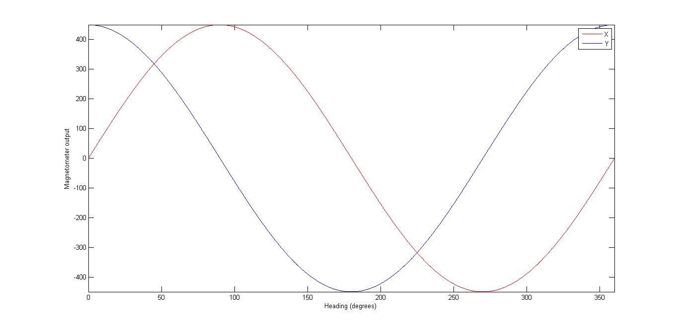
If the sensor was fully calibrated, we held the Engduino perfectly flat and rotated it, keeping the
Engduino flat at all times, then we should see only the x and y values change as they point towards
and away from north. In fact, they should change in this way:
Let’s assume that we can go into an environment (e.g. on a playing field) in which we can be
reasonably sure that the only magnetic field is that due to the earth (buildings have steel in them
and that can have its own magnetic field). If this is the case, we know that what we are measuring is
a constant – it will not change over the course of a set of measurements.
Try the following.
Face North (your phone might have a compass app if you don’t know where this is)
Plug the Engduino into a laptop on a USB extension lead.
Hold the Engduino as flat as you can.
Rotate the Engduino while keeping it flat. You will see the x and y values change and the z will stay about the same.
Find the minimum and maximum values for each of the x and y axes separately.
Actually, this is something that is common to all sensors – for the thermistor, the light sensor or the
accelerometer, we ideally need to know how the value returned from the sensor compares to the
actual truth.
You will be very lucky to see exactly the readings we have above – the x and y values may not be
about ‐450 to +450, but may instead be, say, +232 to 1138 and ‐660 to 253 respectively. So the zero
is likely to be in the wrong place on each axis and the maximum minus the minimum might be
slightly different.
If you move the Engduino about through all the angles you can manage – not even trying to keep it
flat, your max/min values might change a little for x and y, and you will find a range for the z axis. If
you plot the x,y,z values in a 3D scatter plot (unfortunately, Excel doesn’t have one of these, so I
used Matlab) you might get something that looks like the following:
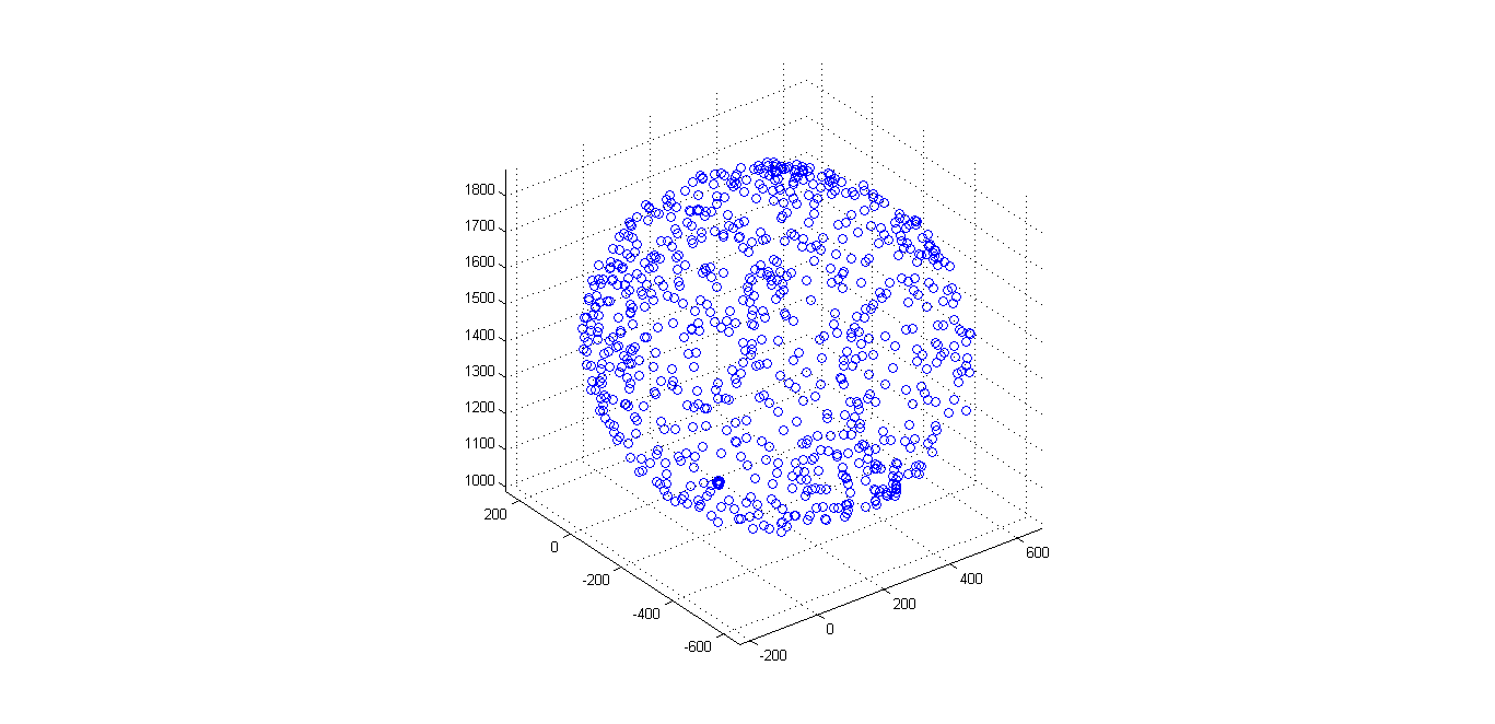
The values lie on (or close to the surface of) a sphere – which is good news, but the sphere isn’t
centred on zero, which is not. Note that, in some cases of magnetic interference, it is possible for the
sphere to distort into an ellipsoid (something that looks more like an egg), which makes life just a
little bit more problematic.
Rather than worry about 3D at this point, let’s see what happens if we just plot the x,y values (for
which you can use Excel), the picture we see is just as if we were looking down on the top of the
sphere along the z axis:
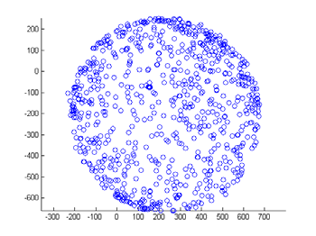
This isn’t quite a circle but it’s fairly close (there is some distortion or the sensor is slightly wonky).
What we would like to do is to move the centre of the circle to (0, 0), so that if you hold the
Engduino flat, we can work out which direction you’re facing in. One simple way of estimating the
centre is just to take the maximum value in each dimension, subtract the corresponding minimum
value and divide by 2. We then subtract the coordinates of that centre point from any value we see –
and the result should be a circle centred (roughly) at the origin.
Given we have this, we can calculate direction using simple trigonometry. Take a look at the heading
graph above, and see if you can work out what the function should be. Hint: arctangent is in the
right area, but it only gives a value between ‐90° and +90°. In many programs, you can use a function
atan2 to give you a value between ‐180° and +180°.
- MORE ADVANCED FUNCTIONS
The above approach is very simplistic. It will give the wrong result if you tip the Engduino out of
horizontal and it takes no account of the case in which the points lie on an ellipsoid rather than a
sphere.
Doing this right involves two things: (i) calibrating the sensor properly against an ellipsoid2; (ii)
compensating for tilt in the Engduino by using the accelerometer to tell us what orientation the
magnetometer is being held in3. This in turn involves some linear algebra.
- CHALLENGE YOURSELF
Calibrate your magnetometer. Find out whether the calibration stays (about) the same over a number of days and whether it is the same inside or outside a building or near something that has a lot of steel in it (e.g. a lift).